Power Quality Analyzer: What It Measures and How to Choose One
A power quality analyzer records voltage, current, harmonics and unbalance so you can see what a supply is really doing. This guide explains what the instrument measures, how analysis differs from monitoring, and how to choose a model for panels, substations and plant surveys.
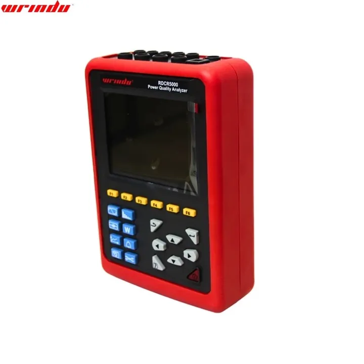
What a Power Quality Analyzer Measures on Site
A power quality analyzer is a high-precision testing device built to detect and evaluate power quality problems in the electrical grid, including waveform distortion, harmonic content and phase unbalance. It is also a portable detection device for evaluating and monitoring how a grid is operating. On site it records voltages and currents, shows the harmonic content of those waveforms, indicates phase unbalance and captures events. Utilities, substations and electrical contractors use it before committing to corrective work.
The instrument is connected where the supply that matters can be seen: a substation secondary, a plant main switchboard, a distribution panel or the terminals of a machine that trips without explanation. Leads clip to the phases and neutral, and current clamps go around the conductors. Spelling varies between suppliers and countries, but a power quality analyser is the same instrument as a power quality analyzer, and both describe the same waveform distortion, harmonic content and phase unbalance, so a specification written with either term can be compared line by line.
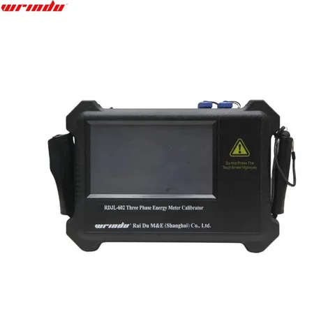
Power quality analyzer, view 2 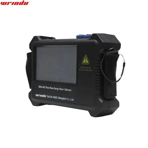
Power quality analyzer, view 3
Power quality analyzer models and specifications
| Parameter | Value |
|---|---|
| Model | RDJL-602 |
| Voltage | 2 ~ 450V, automatic conversion limit, minimum resolution 0.01V |
| Current | built in CT 0.1-5A, accuracy 0.05 grade (10A optional) External clamp CT: 0.1 ~ 5 A, accuracy is 0.1 grade (10A optional) |
| Power measurement | Active power: 0 ~ 99999W, minimum resolution: 0.01W |
| Power measurement | Total active power: 0-999999W, minimum resolution: 0.01 W |
| Power measurement | Reactive power: 0 ~ 99999Var, minimum resolution: 0.01Var |
| Power measurement | Total reactive power: 0-999999 Var, minimum resolution: 0.01Var Power factor: 0.001 ~ 1, minimum resolution: 0.0001 |
| Phase angle | 0 ~ 359.9 º , minimum resolution 0.0001º |
| Frequency | 45 ~ 55Hz, resolution: 0.0001hz |
| Working temperature | – 20 ℃~+ 50 ℃ |
| Working power supply | AC 80V ~ 265V |
| Power consumption | ≤ 3VA |
| Model | RDML-400A | |||
|---|---|---|---|---|
| Measurement function | Measurement range | Measurement range | Resolution | Basic error |
| Voltage | AC 0.00V~600V | AC 0.00V~600V | 0.01V | ± (0.5% range) |
| Current | AC 0.0mA~20.0A | AC 0.0mA~20.0A | 0.1mA | ± (0.5% range) |
| Phase position | 0.0°~360° | 0.0°~360° | 0.1° | ±1° |
| Active power p | 0.0W~12kW | 0.0W~12kW | 0.1W | ± (1.0% range) |
| Reactive power Q | 0.0var~12kvar | 0.0var~12kvar | 0.1var | ± (1.0% range) |
| Apparent power s | 0.0VA~12kVA | 0.0VA~12kVA | 0.1VA | ± (1.0% range) |
| Frequency f | 45Hz~65Hz | 45Hz~65Hz | 0.01Hz | ± (1.0% range) |
| Power factor PF | -1~+1 | -1~+1 | 0.001 | ±0.03 |
| Power Supply | DC 9V 5#battery 1.5V (LR06) x6 | |||
| Jaw size | Φ8mm | |||
| LCD size | 2.8-inch TFT | |||
| Data storage | 500 groups | |||
| Data upload function | USB interface, the stored data uploaded to the computer, easy to analyze and manage data | |||
| Automatic shutdown | Automatic shutdown in 15 minutes | |||
| Power | Turn on backlight: the maximum working current is about 80mA, and the battery works continuously for 8 hours | |||
| Power | Turn off the backlight: the working current is about 50mA, and the battery works continuously for 12 hours | |||
| Work environment | -10 ℃ ~ 40 ℃; below 80% RH | |||
| Storage environment | -10 ℃ ~ 60 ℃; below 70% RH | |||
| phase sequence | Normal phase: U1, U2, U3 or I1, I2, I3 cursor flashes from left to right | |||
| phase sequence | Reverse phase: U1, U2, U3 or I1, I2, I3 cursor flashes from right to left | |||
| Test line length | 1.5m | |||
| Current clamp wire length | 2 m | |||
| Measuring time | 2 seconds/time | |||
| Data hold | During the test, press the HOLD key to keep the data, “ HD ” symbol is displayed | |||
| Input impedance | The input impedance of the test voltage is 1MΩ | |||
| Low battery | When the battery voltage is lower than 7.2V, the symbol of low battery voltage will be displayed to remind you to replace the battery | |||
| Pressure resistance | The instrument circuit and the enclosure withstand 1000V / 50Hz sine wave AC voltage for 1 minute | |||
| Insulation | Between instrument circuit and sheath shell ≥ 100 MΩ | |||
| Structure | Double insulation, with insulating anti vibration sheath |
| Parameter | Value |
|---|---|
| Model | RDXZ-2 |
| Power supply | No. 5 batteries (LR6) ×2 |
| Jaw size | The external diameter of the clampable conductor is Φ1.6mm~Φ16mm |
| Voltage range | AC 70~1000V |
| Automatic shutdown | It will shut down automatically in about 5 minutes |
| Working environment | -10 ~ 50 ℃, below 80% RH |
| Storage environment | -20 ~ 60 ℃, below 90% RH |
| LED display | [positive phase] Four phase detection lamps turn on clockwise; |
| LED display | [reverse phase] Four phase detection lamps turn on in turn in a counterclockwise direction; |
| LED display | [live electricity] L1, L2 and L3 lights are on within the voltage setting range; |
| LED display | [lack of phase] L1 or L2 or L3 lights are not on; |
| LED display | [open circuit] L1 or L2 or L3 lights are not on. |
| Beeps | [positive phase] The instrument makes intermittent short sounds; |
| Beeps | [reverse phase] The instrument sounds continuously. |
| Battery check | After the power is turned on, the power indicator light is on; when the power is insufficient, the Low Battery light is on |
| magnetic force | There are four magnets attached to the back of the instrument, which can be hung on the power distribution box and can withstand the weight of 800g |
| Clamp lead length | 0.6m |
| maximum voltage | AC1000V |
| Insulation strength | 5.4kVrms |
| Maximum rated power | 300mVA |
| product quality | About 215g (including battery) |
| product size | Width x Height x thickness: 70mm × 75mm × 30mm |
| Parameter | Value |
|---|---|
| Function | Description |
| Power supply | Rechargeable lithium-ion battery packs 9.6V, backup charger. |
| Battery Level indicator | Battery symbol 5 grid Display power, when the battery level is low, automatically shut down after a 1-minute indication |
| Working Current | about 590mA, continuous working 8hours. |
| Display mode | LCD color screen, 640×480, 5.6 inches, display field 116mm × 88mm |
| Instrument Size | 240mm×170mm×68 mm. |
| CT Size | 008B small sharp current clamp: 7.5mm×13mm; (optional) 040B round jaw current clamp: 35mm×40mm; (optional) 068B round jaw current clamp: 68mm×68mm. (optional) 300F Flexible Coil Current Sensor (with Integrator): Ø300mm (optional) |
| Number of channels | 4 voltages, 4 currents |
| Line Voltage | 1.0V~2000V. |
| Phase Voltage | 1.0V~1000V. |
| Current | 008B small sharp current clamp: 10mA~10.0A; (optional) 040B round jaw current clamp: 0.10A~100A; (optional) 068B round jaw current clamp: 1.0A~1000A; (optional) 300F Flexible Coil Current Sensor (with Integrator): 10A ~ 6000A (optional) |
| Frequency | 40Hz~70Hz. |
| Electricity Energy Parameter | W, VA, Var, PF, DPF, cosφ, tanφ. |
| Energy parameters | Wh, Varh, Vah. |
| Harmonic Wave | Yes, 0 – 50 times |
| Total harmonic distortion | Yes, 0 – 50 times, each phase |
| Expert Mode | Yes. |
| Transient Record Groups | 150 groups |
| Voltage Flicker | Yes |
| Start Current Mode | Yes, 100 seconds |
| Three-phases Unbalance | Yes |
| Record | 300 days (record 20 parameters simultaneously, every 5 seconds record 1 point) |
| Min/Max Recorded Value | Yes, the max-min value can be measured for a certain time |
| Alarm | 40 different types of parameter selection, 12800 group alarm logs |
| Peak | Yes. |
| Phasor Diagram Display | Automatic |
| Screenshot Capacity | 60PCS |
| Menu language | English/Chinese. |
| Communication Interface | USB. |
| Automatic Shut Down | In the alarm/trend graph recording/transient capture mode (waiting or in progress), the instrument does not automatically shut down |
| Automatic Shut Down | In other test modes, there is no button operation within 15 minutes, prompting to automatically shut down after 1 minute. |
| Backlight Function | Yes, it is suitable for dark places and nighttime use |
| Instrument Weight | Host: 1.6kg (with battery). |
| Instrument Weight | 008B small sharp current clamp: 170g×4; (optional) |
| Instrument Weight | 040B round jaw current clamp: 190g×4; (optional) |
| Instrument Weight | 068B round jaw current clamp: 510g×4; (optional) |
| Instrument Weight | 300F Flexible Coil Current Sensor (with Integrator): 330g×4; (optional) |
| Instrument Weight | Test wires and power adapter: 900g; |
| Instrument Weight | Total weight: about 9.2kg (with package). |
| Voltage Test Wire Length | 3m |
| Current Clamp Wire Length | 2m |
| Working Temperature | -10°C~40°C; below 80%Rh. |
| Storage Temperature | -10°C~60°C; below 70%Rh. |
| Input Impedance | Test voltage input impedance: 1MΩ |
| Withstand voltage | Withstand the sine wave AC voltage of 3700V/50Hz one minute between the instrument line and out shell |
| Insulation | Between instrument line and shell ≥10MΩ. |
| Structure | Double insulation, with insulation shock-proof sheath. |
| Parameter | Value | ||
|---|---|---|---|
| Measurement Specification | Range | Display Resolution | Max Error of Reference Range |
| Frequency | 40Hz~70Hz | 0.01Hz | ±(0.03)Hz |
| Phase Voltage True RMS | 1.0V~1000V | Min resolution 0.1V | ±(0.5%+5dgt) |
| Line Voltage True RMS | 1.0V~2000V | Min resolution 0.1V | ±(0.5%+5dgt) |
| DC Voltage | 1.0V~1000V | Min resolution 0.1V | ±(1.0%+5dgt) |
| Current True RMS | 10mA~1000A | Min resolution 0.1mA | ±(0.5%+2dgt) |
| Phase Voltage Peak | 1.0V~1414V | Min resolution 0.1V | ±(1.0%+5dgt) |
| Line Voltage Peak | 1.0V~2828V | Min resolution 0.1V | ±(1.0%+5dgt) |
| Current Peak | 10mA~1414A | Min resolution 0.1mA | ±(1.0%+5dgt) |
| Peak Factor | 1.00~3.99 | 0.01 | ±(1%+2dgt) |
| Peak Factor | 4.00~9.99 | 0.01 | ±(5%+2dgt) |
| Active Power | 0.000W~9999.9kW | Min resolution 0.001W | ±(1%+3dgt); Cosφ≥0.8 |
| Active Power | 0.000W~9999.9kW | Min resolution 0.001W | ±(1.5%+10dgt); 0.2≤Cosφ<0.8 |
| Reactive power Inductive& Capacitive | 0.000Var~9999.9kVar | Min resolution 0.001Var | ±(1%+3dgt);Sinφ≥0.5 |
| Reactive power Inductive& Capacitive | 0.000Var~9999.9kVar | Min resolution 0.001Var | ±(1.5%+10dgt); 0.2≤Sinφ<0.5 |
| Apparent Power | 0.000VA~9999.9kVA | Min resolution 0.001VA | ± (1%+3dgt %) |
| Active Energy | 0.000Wh~9999.9MWh | Min resolution 0.001Wh | ±(1%+3dgt); Cosφ≥0.8 |
| Active Energy | 0.000Wh~9999.9MWh | Min resolution 0.001Wh | ±(1.5%+10dgt); 0.2≤Cosφ<0.8 |
| Reactive Energy Inductive& Capacitive | 0.000Varh~9999.9MVarh | Min resolution 0.001Varh | ±(1%+3dgt);Sinφ≥0.5 |
| Reactive Energy Inductive& Capacitive | 0.000Varh~9999.9MVarh | Min resolution 0.001Varh | ±(1.5%+10dgt); 0.2≤Sinφ<0.5 |
| Apparent Energy | 0.000VAh~9999.9MVAh | Min resolution 0.001VAh | ±(1%+3dgt) |
| Phase Angle | -179°~180° | 1° | ±(2°) |
| HarmonicRatio (Vrms>50V) | 0.0 %~99.9 % | 0.1 % | ±(1%+5dgt) |
| Harmonic Angle(Vrms >50V) | -179°~180° | 1° | ±(3°)harmonic1~25 |
| Harmonic Angle(Vrms >50V) | -179°~180° | 1° | ±(10°)harmonic26~50 |
| Total Harmonic Rate (DF or THD-F)≤50 | 0.0 %~99.9 % | 0.1 % | ±(1%+5dgt) |
| Distortion Factor (DF or THD-R)≤50 | 0.0 %~99.9 % | 0.1 % | ±(1%+10dgt) |
| Transformer K Factor | 1.00~99.99 | 0.01 | ±(5 %) |
| Three-phase Unbalance | 0.0%~100 % | 0.1 % | ±(1 %) |
| Parameter | Value | |||
|---|---|---|---|---|
| Current sensor model | Current Clamp | Current True RMS | Current True RMS Max Error | Phase Angle φ Max Error |
| 008B small sharp current clamp: 7.5mm×13mm | 10mA~99mA | ±(1%rdg+3dgt) | ±(1.5°),Arms≥20mA | |
| 008B small sharp current clamp: 7.5mm×13mm | 100mA~10.0A | ±(1%rdg+3dgt) | ±(1°) | |
| 040B round jaw current clamp:Ø40mm | 0.10A~0.99A | ±(1%rdg+3dgt) | ±(1.5°) | |
| 040B round jaw current clamp:Ø40mm | 1.00A~100A | ±(1%rdg+3dgt) | ±(1°) | |
| 068B round jaw current clamp:Ø68mm | 1.0A~9.9A | ±(2%rdg+3dgt) | ±(3°) | |
| 068B round jaw current clamp:Ø68mm | 10.0A~1000A | ±(2%rdg+3dgt) | ±(2°) | |
| 300F Flexible Coil Current Sensor:Ø300mm | 10A~99A | ±(1%rdg+3dgt) | ±(3°) | |
| 300F Flexible Coil Current Sensor:Ø300mm | 100A~6000A | ±(1%rdg+3dgt) | ±(2°) |
What Is Power Quality Analysis and What Problems Does It Reveal?
Power quality analysis is the interpretation step that follows measurement. Recorded voltage and current waveforms and their harmonic content are compared with expected values to see where distortion, harmonics and phase unbalance appear and over which part of the duty cycle. From that comparison the analyst traces the likely source — a drive, an unbalanced single-phase load, a loose neutral — and turns the finding into a corrective action: load rebalancing, filtering, a different connection point or further investigation.
The problems uncovered are practical. Distorted current heats neutral conductors and transformer windings, unbalance loads one phase while the others idle, and harmonic resonance can trip protective devices that have no fault to clear. When a breaker trips with no fault present, recorded waveforms are read alongside circuit-breaker analyzer results to separate supply problems from switching problems.
Power Analyzers and Power Quality Meters: What Is the Difference?
Power analyzers measure and characterise the electrical power in a circuit: how much flows through it, in what direction, and how efficiently the equipment uses it. They answer questions about power, power factor, energy and load behaviour. Power quality instruments look instead at the condition of the supply — waveform shape, harmonic content, unbalance and events. The two overlap in the middle, since a power analyzer also reports waveform and power factor data.
Power quality meters are the instrument form used where readings are taken at a panel, a distribution board or a fixed measurement point. Against a portable analyzer they differ on three-phase capability, recording versus spot reading, portability, and how results are exported for reporting. Choose by task: an efficiency check on a drive or motor suits a power analyzer; unexplained distortion suits a power quality analyzer; a problem that reappears at one point over weeks suits a fixed meter or a logger.
Long-Term Power Quality Monitoring and When You Need a Power Quality Logger
Power quality monitoring is repeated or continuous recording over a period, so that intermittent events, load-dependent distortion and slow trends are captured rather than missed by a single snapshot. Voltages, current, harmonics, unbalance and events are logged with time stamps, and the record supports maintenance planning and fault-finding. A spot measurement is enough when the problem is present while the instrument is connected; monitoring suits complaints that appear only at certain shifts, seasons or loading conditions.
The logger is the instrument that does this work: connected at a fixed point and left in place, it runs unattended while the plant operates normally, recording the channels and values set at commissioning, and its stored data is exported afterwards for reporting. For field work on three-phase systems, Wrindu supplies the RDCR5000 Power Quality Analyzer, a comprehensive test instrument specially designed for field test of three phases, multi-functional and intelligent, with concise man-machine operation.
Choosing a 3 Phase Power Analyzer for Panels and Substations
Three-phase work needs simultaneous measurement on all phases, because the values that matter cannot be derived from single-phase readings. Phase-to-phase and phase-to-neutral voltages are measured at the same instant, phase unbalance is computed from the three phasors, and per-phase harmonic content shows whether one phase carries distortion the others do not see. Sequential single-phase checks miss the timing that unbalance and harmonics depend on, which is why substation and industrial panel surveys are made with a three-phase instrument.
Wrindu supplies the RDCR5000 Power Quality Analyzer, an instrument specially designed for field test of three phases, multi-functional and intelligent, with concise man-machine operation. Wrindu also provides OEM and ODM customized products where a different configuration or branding is needed. Other instruments for the same visit can be specified in the same order, such as transformer test equipment or a ground resistance tester.
Power Quality Testing: How an On-Site Survey Is Carried Out
An on-site survey follows a settled order of work, and the result depends as much on how the survey is set up as on the instrument itself. The steps below describe a first survey with a portable analyzer.
- Agree the objective and the exact point of connection before opening a panel.
- Connect with leads and clamps suited to the installation, and confirm range and phase order.
- Record with the plant running normally, then under the load condition that causes the complaint.
- Compare harmonics, unbalance and waveform distortion against expected values and against the other phases.
- Set out findings with recommended actions.
The report is part of the test: recorded waveforms, harmonic tables and event lists should be arranged so a maintenance planner can act on them. Where the survey points to connection or insulation problems rather than supply problems, the visit can be extended with an insulation resistance tester.
Wrindu Supply, Delivery and Support for Power Quality Analyzers
Wrindu is the brand name of Rui Du Mechanical and Electrical (Shanghai) Co., Ltd., which specializes in power testing equipment. The company was established in 2014, is located in Shanghai, China, and has over 10 years of professional experience in global market service. Wrindu has exported products to more than 120 countries, with South Asia, Southeast Asia and Africa as its main markets.
The normal order runs from the test object, voltage level and tests needed to a selection proposal, then order, pre-delivery inspection and packing, shipping, and training. Many Wrindu listings on its Alibaba store show a minimum order of 1 set. Payment is by T/T or PayPal in USD or CNY, delivery terms are FOB and express delivery, and the nearest port is Shanghai.
During the 12-month warranty Wrindu provides free training, manuals, complaint response and software upgrades. The after-sales team offers installation, training and maintenance support, and maintenance and spare parts remain available after the warranty ends.
Request a quotation
Share the equipment under test and the tests you plan to run.
Or write to sales@hipottestequipment.com