Transformer Oil Tester: A Guide to Oil Testing and Dissolved Gas Analysis
Oil condition is a clear indicator of transformer health. This guide explains the tests used in an oil programme, the instruments that perform them, and how dissolved gas results guide maintenance decisions.
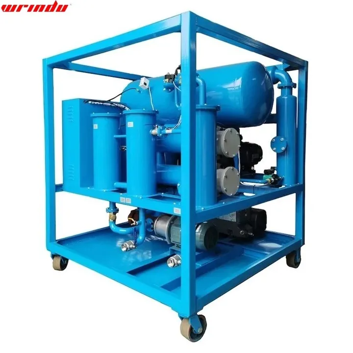
What a Transformer Oil Tester Measures
A transformer oil tester applies a controlled high voltage across an oil sample and raises it until breakdown occurs, so the result is the oil’s dielectric breakdown voltage. That measurement shows whether moisture, particles or ageing products have weakened the insulating strength. Oil work also covers moisture content, dielectric loss and resistivity, gas content and dissolved gas analysis, and each measurement answers a different condition question. Wrindu is a Shanghai-based supplier of power testing equipment, established in 2014, and has exported products to more than 120 countries. The sections below route you to the oil condition you are checking.
Breakdown voltage is the usual initial check because it gives a quick view of overall oil condition. Moisture and acidity tests show contamination and ageing, dielectric loss and resistivity show the condition of the liquid insulation, and gas content or dissolved gas analysis shows what is happening inside the transformer. Use the test result to decide whether the next step is filtration, treatment or further electrical diagnosis. Electrical follow-up is grouped under transformer test equipment.
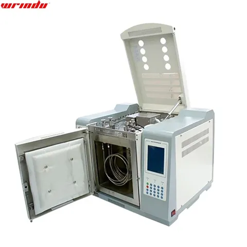
Insulating oil tester, view 2 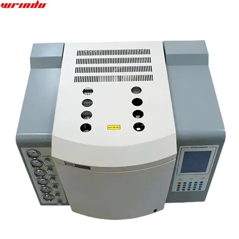
Insulating oil tester, view 3
Transformer oil tester models and specifications
| Parameters | Parameters | Model Unit | ZYD-30 | ZYD -50 | ZYD -100 | ZYD -150 | ZYD -200 | ZYD-250 | ZYD -300 |
|---|---|---|---|---|---|---|---|---|---|
| Flow Rate | Flow Rate | Liter/hour | 1,800 | 3,000 | 6,000 | 10,000 | 12,000 | 15,000 | 18,000 |
| Recommended Max. oil volume in one storage tank | Recommended Max. oil volume in one storage tank | Tons | 6 | 12 | 24 | 40 | 60 | 90 | 110 |
| Relative Working Vacuum Degree | Relative Working Vacuum Degree | MPa | -0.08 ~ -0.099 MPa | -0.08 ~ -0.099 MPa | -0.08 ~ -0.099 MPa | -0.08 ~ -0.099 MPa | -0.08 ~ -0.099 MPa | -0.08 ~ -0.099 MPa | -0.08 ~ -0.099 MPa |
| Absolute Operating Vacuum Level | Absolute Operating Vacuum Level | Pa | ≤ 8 Pa | ≤ 8 Pa | ≤ 8 Pa | ≤ 8 Pa | ≤ 8 Pa | ≤ 8 Pa | ≤ 8 Pa |
| Working Discharge Pressure | Working Discharge Pressure | MPa | ≤ 0.5 | ≤ 0.5 | ≤ 0.5 | ≤ 0.5 | ≤ 0.5 | ≤ 0.5 | ≤ 0.5 |
| Vacuum Pump Capacity | Vacuum Pump Capacity | M3/hr | For preliminary rotary vane vacuum pump: 200 m3/hr For booster roots vacuum pump: 1000 m3/hr | For preliminary rotary vane vacuum pump: 200 m3/hr For booster roots vacuum pump: 1000 m3/hr | For preliminary rotary vane vacuum pump: 200 m3/hr For booster roots vacuum pump: 1000 m3/hr | For preliminary rotary vane vacuum pump: 200 m3/hr For booster roots vacuum pump: 1000 m3/hr | For preliminary rotary vane vacuum pump: 200 m3/hr For booster roots vacuum pump: 1000 m3/hr | For preliminary rotary vane vacuum pump: 200 m3/hr For booster roots vacuum pump: 1000 m3/hr | For preliminary rotary vane vacuum pump: 200 m3/hr For booster roots vacuum pump: 1000 m3/hr |
| Temperature Control | Temperature Control | ℃ | 0 ~ 100 | 0 ~ 100 | 0 ~ 100 | 0 ~ 100 | 0 ~ 100 | 0 ~ 100 | 0 ~ 100 |
| Power Supply | AC 3~, 380 V, 50Hz, 4 Wire (or as per your requirements) | ||||||||
| Operation Mode | Continuous Operation | ||||||||
| Working hours without Trouble | Working hours without Trouble | Hour | 4000 | 4000 | 4000 | 4000 | 4000 | 4000 | 4000 |
| Continuous Working Hours | Continuous Working Hours | Hour | 150 | 150 | 150 | 150 | 150 | 150 | 150 |
| Ambient Temperature | -25 ~ 55℃ | ||||||||
| Working Noise | Working Noise | dB(A) | 65 ~ 85 | 65 ~ 85 | 65 ~ 85 | 65 ~ 85 | 65 ~ 85 | 65 ~ 85 | 65 ~ 85 |
| Cooling Method | Air Cooling | ||||||||
| Heating Power (adjusted available) | Heating Power (adjusted available) | KW | 30 | 72 | 90 | 120 | 135 | 150 | 180 |
| Total Power | Total Power | KW | 36 | 78 | 105 | 136 | 150 | 170 | 206 |
| Inlet/Outlet | Inlet/Outlet | mm | φ25 | Φ32 | φ50 | φ50 | φ50 | φ60 | φ60 |
| Weight | Weight | Kg | 500 | 900 | 1200 | 1400 | 1650 | 1800 | 1950 |
| Dimension | Length | mm | 1380 | 1710 | 1800 | 2010 | 2060 | 2100 | 2200 |
| Dimension | Width | mm | 1020 | 1510 | 1560 | 2030 | 2100 | 2150 | 2250 |
| Dimension | Height | mm | 1760 | 1860 | 2080 | 2080 | 2200 | 2450 | 2550 |
| After Treatment | After Treatment | ||||||||
| Dielectric Strength | Dielectric Strength | kV | ≥ 70 ~ 80 | ≥ 70 ~ 80 | ≥ 70 ~ 80 | ≥ 70 ~ 80 | ≥ 70 ~ 80 | ≥ 70 ~ 80 | ≥ 70 ~ 80 |
| Water Content | Water Content | PPM | ≤ 5 | ≤ 5 | ≤ 5 | ≤ 5 | ≤ 5 | ≤ 5 | ≤ 5 |
| Gas Content | Gas Content | % | ≤ 0.1 | ≤ 0.1 | ≤ 0.1 | ≤ 0.1 | ≤ 0.1 | ≤ 0.1 | ≤ 0.1 |
| Particle Size | Particle Size | μm | ≤ 3 | ≤ 3 | ≤ 3 | ≤ 3 | ≤ 3 | ≤ 3 | ≤ 3 |
| Parameter | Value |
|---|---|
| Model | RDSP-3401 |
| Normal Working Conditions Of The Instrument | Normal Working Conditions Of The Instrument |
| Ambient temperature | 5 ~ 35 ℃ |
| Relative humidity | 0 ~ 85%RH |
| There is no strong electromagnetic interference or corrosive gas around | There is no strong electromagnetic interference or corrosive gas around |
| The placement table shall be stable without strong vibration | The placement table shall be stable without strong vibration |
| Power supply | AC 220 V ± 10%, 50 Hz ± 0.5 Hz |
| Power consumption | About 2.5kW |
| The Main Technical Indicators | The Main Technical Indicators |
| Temperature control area | 8 ways |
| Temperature control range | -Room temperature above 5 ℃ ~ 400 ℃. -Increment:1 ℃. -Accuracy: ±0.1 ℃ |
| Temperature-programmed order | 16 orders |
| Temperature-programmed range | 0.1~60℃/min |
| The gas control | Precision mechanical valve flow control |
| External events | 8 channels; Auxiliary control output (2 channels) |
| Chromatographic column | Special column for transformer oil |
| Number of detectors | Up to 3, default to FID and TCD (ECD, FPD and NPD are optional) |
| Start sampling | Manual, automatic optional |
| Communication interface | Ethernet IEEE802.3 |
| Detector Technology Index | Detector Technology Index |
| Hydrogen flame ionization detector (FID) | Hydrogen flame ionization detector (FID) |
| The limit of detection | ≤ 5×10 -12 g/s (sixteen alkyl) |
| Baseline noise | ≤7×10 -14 A |
| Baseline drift | ≤2×10 -13 A/30min |
| Linear range | ≥10 6 |
| Thermal conductivity detector (TCD) | Thermal conductivity detector (TCD) |
| Sensitivity | S ≥ 2500mV•ml/mg (sixteen alkyl) (1, 2, 3, 4 times enlarged, optional) |
| Baseline noise | ≤ 20 μV |
| Baseline drift | ≤ 30 μV/30min |
| Linear range | ≥10 4 |
| Parameter | Value | ||||||
|---|---|---|---|---|---|---|---|
| In two injections, the injection volume is 1ml, and the minimum detection concentration in transformer oil | In two injections, the injection volume is 1ml, and the minimum detection concentration in transformer oil | ||||||
| Component name | H2 | CO | CO2 | CH4 | C2H4 | C2H6 | C2H2 |
| Minimum detection concentration (μL/L) | 2 | 5 | 5 | 0.1 | 0.1 | 0.1 | 0.1 |
| Parameter | Value | |
|---|---|---|
| Gas | Range (ppm) | Resolution |
| Hydrogen (H 2 ) | 5.0 ~ 5000.0 | 2ppm NA |
| Carbon Monoxide (CO) | 1.0 ~ 50,000.0 | 2ppm |
| Carbon Dioxide (CO 2 ) | 2.0 ~ 50,000.0 | 0.1ppm |
| Ethylene (C 2 H 4 ) | 1.0 ~ 50,000.0 | 0.1ppm |
| Ethane (C 2 H 6 ) | 1.0 ~ 50,000.0 | 0.1ppm |
| Methane (CH 4 ) | 1.0 ~ 50,000.0 | 0.1ppm |
| Acetylene (C 2 H 2 ) | 0.5 ~ 50,000.0 | 0.1ppm |
| Moisture (H 2 O) | ≥5ppm | 2ppm NA |
| Parameter | Value |
|---|---|
| Feature | Details |
| Samples | Oil |
| Samples | Gas |
| PC Port | USB |
| Printing Output | 2 inch mini printer |
| Power | AC100~250V, 47~63Hz, 12W |
| Host Dimension | 524mm × 428mm × 206mm |
What Dissolved Gas Analysis Tells You About a Transformer
Insulating oil absorbs gases generated by thermal and electrical stress. Individual gases point to different mechanisms: hydrogen to partial discharge, methane and ethylene to overheating, acetylene to arcing, and carbon oxides to paper or oil degradation. A rising gas pattern is among the earliest indicators of a developing internal fault. An isolated reading is less useful than the change between samples.
Dissolved gas analysis follows a general workflow: sample the oil, extract the dissolved gases, separate them chromatographically, and compare the results with earlier samples. Wrindu supplies the RDZD-3402 sample-preparation oscillator for the extraction step and the RDSP-3401 insulating oil gas chromatography analyzer for the separation step; the RDSP-3401 uses a large-screen LCD display and keyboard parameter setting.
Transformer dissolved gas analysis tracks the concentration and ratios of individual gases in the oil. The ratios help classify likely fault types such as partial discharge, overheating or arcing, and the trend shows whether a fault is active or slowly developing. The diagnostic step is ratio-based interpretation compared with earlier samples, not an isolated reading.
Run DGA for a commissioning baseline, at routine intervals during service, immediately after a fault or protection operation, and before and after oil treatment. The interval follows asset criticality and the trend of previous results; the initial sample establishes the baseline. To act on results, compare gas concentrations and ratios with reference limits and earlier samples, classify the probable fault, then resample to confirm, increase monitoring frequency, or investigate with electrical tests. Follow-up work can use the RDZR-350X Transformer DC Resistance Tester, RDB-IIHX Portable Transformer Turn Ratio Tester, RD6000C Transformer Tan Delta Test Kit and RDPDZ-104H Partial Discharge Tester.
Why Transformer Oil Testing Is Part of Substation Maintenance
Transformer oil testing is a routine condition check, not a fault-finding exercise carried out only after a failure. A sample is drawn correctly from the bottom valve so that it represents the oil in service, then tested for breakdown voltage, moisture, acidity, dielectric loss and gas content. Results are trended against earlier samples, because a change over time is more informative than an isolated pass or fail reading.
The trend drives maintenance decisions. A falling breakdown voltage or rising moisture may call for oil filtration or oil treatment; a changing gas pattern may call for further electrical diagnosis. Maintenance teams use the same samples to plan outages and to confirm that treatment has worked. Oil testing therefore sits alongside electrical tests in a substation maintenance programme. Further electrical diagnosis can include tan delta testing on bushings and windings.
Insulating Oil Tester Types and What Each One Checks
An insulating oil tester is selected by the oil property you need to measure. Breakdown voltage testers check dielectric strength; moisture testers check water content; dielectric loss and resistivity instruments check the condition of the liquid insulation; gas content testers check total dissolved gas; and DGA instruments identify individual gases. Wrindu supplies the Insulation Oil Volume Resistivity Test Equipment, which provides dielectric loss factor and DC resistivity measurements for insulating oil and other liquid-insulating materials. That instrument covers dielectric loss and resistivity, not breakdown voltage or gas content.
The RDHQ-3701 insulating oil gas content tester is a professional device for gas content in oil. It covers total gas content, which is a different measurement from the individual gas concentrations reported by dissolved gas analysis. Match the instrument to the test plan: use the volume resistivity equipment for dielectric loss and DC resistivity, the RDHQ-3701 for gas content, and the DGA instruments covered further down the page when you need gas-by-gas analysis. A buyer who needs breakdown voltage should select a dedicated breakdown voltage tester rather than these instruments.
Choosing a Transformer Dissolved Gas Analyzer
The RDSP-3411 Portable Insulation Oil DGA Tester is a next-generation tool for analysing dissolved gases in oil. The RDSP-3401 insulating oil gas chromatography analyzer uses a large-screen LCD display and keyboard parameter setting for laboratory chromatography work. The RDHQ-3701 insulating oil gas content tester measures total gas content rather than individual gases. These instruments serve different workflows: the portable unit supports field use, the chromatograph supports laboratory separation, and the gas content tester gives a total gas check.
Portable and laboratory workflows differ in sample handling. A portable DGA tester is used where samples cannot be moved promptly or where a field check is needed. A laboratory chromatograph requires controlled sample preparation and separation. The gas content tester is a simpler check for total gas. Selection also depends on the sample volume, the gases of interest and the follow-up electrical tests available.
- Field use, laboratory use, or a shared programme
- Individual gas concentrations, gas ratios, or total gas content as the required output
- How oil samples will be taken, transported and prepared
- Which electrical follow-up tests are available if DGA indicates a possible fault
Request a quotation
Share the equipment under test and the tests you plan to run.
Or write to sales@hipottestequipment.com