Ground Resistance Tester for Utilities and Substations
A ground resistance tester checks how well a grounding system or electrode connects to earth. Wrindu supplies clamp-based and stake-based models for substation, utility and contractor grounding work, and helps buyers match the instrument to the measurements a site needs.
- Warranty
- 12-month warranty
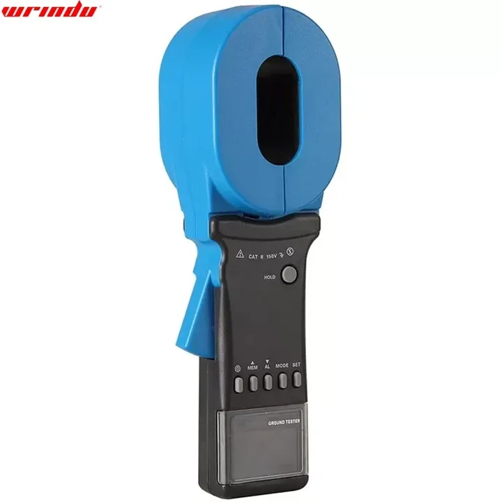
Ground Resistance Testers for Substation and Contractor Work
The right ground resistance tester depends on what the crew must check: the resistance of a single electrode, the condition of a grounding grid, soil resistivity at the test location, or the voltage present on a grounding lead. Clamp-based instruments read through an existing grounding conductor, while stake-based instruments inject a signal through auxiliary probes driven into the soil. Wrindu supplies both types for substation, utility and contractor work.
Selection starts with the test object, the voltage level of the installation and the measurements required. Send those details through the inquiry form or the sales email, and Wrindu will propose the model that covers them. The contact page reaches the same sales team for a quotation.
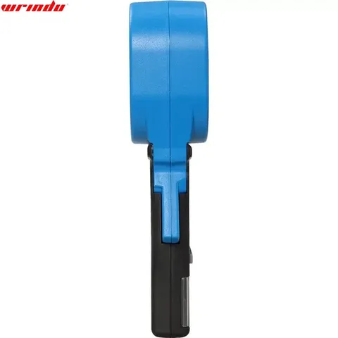
Ground resistance tester, view 2 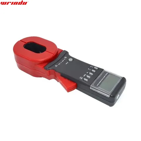
Ground resistance tester, view 3
Ground resistance tester models and specifications
| Model | RDER2000A+ | RDER2100A+ |
|---|---|---|
| Picture | ||
| Clamp Size | 65mm×32mm | Φ32mm |
| Tester Weight | 1160g | 1030g |
| Tester Dimension | L×W×T: 285mm×85mm×56mm | |
| Function | Description | |
| Power Supply | 6VDC 4 PCS LR6 alkaline batteries | |
| LCD Size | 4 Digits LCD, Screen: 47mm×28.5mm | |
| Range | 0.010Ω ~1200Ω | |
| Resolution | 0.001Ω | |
| Accuracy | ±1% ± 0.01Ω | |
| Data Storage | 99 sets | |
| Data Upload Function | RS232 Interface (Optional) | |
| Auto Shutdown | Automatically power off after 5 minutes without any operate | |
| Power Consumption | ≤50mA, continuously working for 30 hours | |
| Working Environment | -20℃~55℃; 20%~80% RH | |
| Store Environment | -20℃~60℃; below 90% RH | |
| Alarm Threshold Setting Range | Resistance: 1Ω~199Ω | |
| Audible and VisibleAlarm | “Beep-beep-beep” alarm sound, alarm symbol flashing, press AL key to turn on/off and setting | |
| Interference Signal Recognition | “Beep-beep-beep” indicator, NOISE symbol blinking | |
| Protection Level | Double insulation | |
| Structural Feature | Clamp CT | |
| Shift | Automatic shift | |
| External Magnetic Field | <40A/m | |
| External Electrical Field | <1V/m | |
| Single Measurement Time | 0.5 second | |
| Resistance Measurement Frequency | >1KHz | |
| Measured Current Frequency | 50/60Hz Automatic | |
| Low Battery Voltage Indicator | When the battery voltage is lower than 5.3V, the low battery voltage symbol is displayed | |
| Storage Full Indication | Storage data full of 99 sets, flashed display “MEM” symbol | |
| Over Range Indication | Exceed range indication “OLΩ”, “L0.01” or “OLA” |
| Model | RDER2000A+ & RDER2100A+ | ||
|---|---|---|---|
| Measurement | Range | Resolution | Accuracy |
| Resistance | 0.010Ω ~ 0.099Ω | 0.001Ω | ± (1% rdg + 0.01Ω) |
| Resistance | 0.10Ω ~ 0.99Ω | 0.01Ω | ± (1% rdg + 0.01Ω) |
| Resistance | 1.0Ω ~ 49.9Ω | 0.1Ω | ± (1% rdg + 0.1Ω) |
| Resistance | 50.0Ω ~ 99.5Ω | 0.5Ω | ± (2% rdg + 0.5Ω) |
| Resistance | 100Ω ~ 200Ω | 1Ω | ± (3% rdg + 1Ω) |
| Parameter | Value |
|---|---|
| Picture | |
| Model | RDDT-10A |
| Name | Technical indicators and parameters |
| Test Current | AUTO, 1A, 3A, 5A, 10A |
| Measuring Range | 0.8mΩ-0.8Ω (10A) 1mΩ-2Ω (5A) 5mΩ-3Ω (3A) 10mΩ-10Ω (1A) |
| Minimum Resolution | 0.1μΩ |
| Accuracy | ± (0.5%±2 digits) |
| Display | LCD, resistance display, 4 significant digits |
| Data Storage | 1000 groups |
| Working Environment | Ambient temperature: 0℃~40℃ Relative humidity <90% RH, no condensation |
| Power Supply | Built-in lithium battery AC 220V±10V, 50Hz±1 Hz, fuse 2A |
| Maximum Power Consumption | 100W |
| Parameter | Value |
|---|---|
| Picture | |
| Model | RDWR-5A |
| Measurement Range | 0~5000Ω (including current pile impedance) |
| Resolution | 0.001mΩ |
| Measurement Error | ± (reading×2% + 0.005Ω) |
| Anti-power Frequency 50 Hz Voltage Interference Ability | 10V |
| Test Current Waveform | Sine Wave |
| Test Current Frequency | Single Frequency: 40-70Hz (resolution: 0.1Hz, settable) |
| Test Current Frequency | Dual Frequency: 50±0.1Hz to 50±10.0Hz (settable) 60±0.1Hz to 60±10.0Hz (settable) |
| Output Current | 5A (can reach 30A using external power supply) |
| Output Voltage | 400V (can reach 1000V using external power supply) |
| Measuring Line Requirements | The cross-sectional area of the copper core of the current line ≥ 1.5mm² |
| Measuring Line Requirements | The sectional area of the copper core of voltage wire ≥ 1.0mm² |
| Measuring Line Requirements | The Measuring line to be provided by the user |
| Test Power Supply | Built-in 2kW variable frequency power supply |
| Power Supply | AC220V±10%, 50Hz |
| Model | RDER2000+ & RDER2100+ | ||
|---|---|---|---|
| Measurement | Range | Resolution | Accuracy |
| Resistance | 0.010Ω ~ 0.099Ω | 0.001Ω | ± (1% rdg + 0.01Ω) |
| Resistance | 0.10Ω ~ 0.99Ω | 0.01Ω | ± (1% rdg + 0.01Ω) |
| Resistance | 1.0Ω ~ 49.9Ω | 0.1Ω | ± (1% rdg + 0.1Ω) |
| Resistance | 50.0Ω ~ 99.5Ω | 0.5Ω | ± (1.5% rdg + 0.5Ω) |
| Resistance | 100Ω ~ 199Ω | 1Ω | ± (2% rdg + 1Ω) |
| Resistance | 200Ω ~ 395Ω | 5Ω | ± (5% rdg + 5Ω) |
| Resistance | 400Ω ~ 590Ω | 10Ω | ± (10% rdg + 10Ω) |
| Resistance | 600Ω ~ 880Ω | 20Ω | ± (20% rdg + 20Ω) |
| Resistance | 900Ω ~ 1200Ω | 30Ω | ± (25% rdg + 30Ω) |
What Ground Testing Measures
Earth ground resistance testing checks a grounding system and its electrodes: whether the buried metal still carries fault current into the soil with low opposition. An earth ground resistance tester is used for that check on substations, poles, buildings and industrial installations, and the readings show whether the grounding path has changed since installation.
A ground tester covers several related measurements. Resistance is measured between an electrode or grid and the surrounding soil. Soil resistivity describes how the ground itself resists current at the test location. Ground voltage shows whether unwanted voltage sits on the grounding system. Clamp-based checks read the loop formed by the grounding conductor and its bonded path without opening the connection.
The choice between these tasks decides the instrument, since a crew testing a single rod works differently from a crew checking a bonded grid. Wrindu models are listed by function on this page. For insulation checks on the same equipment, see insulation resistance testers.
How to Choose a Ground Resistance Meter
Selection starts with the measurement goal and the method it requires. Where the grounding conductor can be clamped, a clamp-based earth resistance meter reads the grounding path quickly. Where soil resistivity or an isolated electrode must be checked, a stake-based instrument with auxiliary probes is the right approach. Site access matters too: hard or paved ground limits where stakes can be driven.
For work that covers ground resistance, soil resistivity, earth voltage and AC voltage, RD3000B is listed for those measurements. RD3031E adds grounding lead leakage current and AC current to its earth resistance, soil resistivity and earth voltage functions. RDWR-5A is supplied for grounding resistance and grid conduction, and RDER2100C+ for clamp-based grounding resistance checks.
A portable earth tester is judged by the measurements it covers, the method it uses and how well it fits the site. Buyers can send the site conditions and the required measurements to Wrindu for a quotation on the exact model needed.
Testing Ground Rods and Electrodes
Ground rod testing checks the connection between a rod or electrode and the surrounding soil. Where the electrode is bonded into a wider grounding system, a clamp-based ground rod tester reads the loop through the grounding conductor without disconnecting it. Where a rod stands alone, a stake-based measurement with auxiliary probes is used instead. Both are general field methods; the model chosen must match the measurement.
Wrindu supplies RD3031E and RDER2100C+ as clamp-based models for grounding resistance checks. RDWR-5A is listed for grounding resistance and grid conduction, which suits ground grids rather than single rods. Grounding checks often sit beside transformer test equipment in a substation programme.
Ground Resistance and Soil Resistivity Basics
Ground resistance is the opposition a grounding system and the surrounding soil present to current flowing into the earth. It depends on the soil, its moisture and mineral content, the depth and surface area of the electrode, and the bonding between electrodes in a grid. A low reading means fault current has an easier path; a rising reading points to drying soil, corrosion or a broken connection.
Soil resistivity describes the soil itself rather than a single electrode, and it is measured to plan a grounding system or to explain why resistance has changed. Electrode and ground grid checks then confirm the installed system. RD3000B, RD3031E, RDER2100C+ and RDWR-5A cover these checks according to their listed functions.
How an order runs
- Send your requirements
- The equipment you need to test, its voltage level and the tests you plan to run.
- Selection and quotation
- Wrindu proposes matching tester models and accessories and sends a quotation.
- Inspection and delivery
- Equipment is inspected and packed before delivery; the delivery time is confirmed with the quotation.
- Warranty and training
- During the 12-month warranty, Wrindu provides free training, manuals, complaint response and software upgrades.
Request a quotation
Send the test object and voltage level; we will propose matching tester models.
Or write to sales@hipottestequipment.com